Industrial Automation PCB Assembly Guide: Design and Manufacturing Priorities for Reliable Control Systems
SUNTOP Electronics
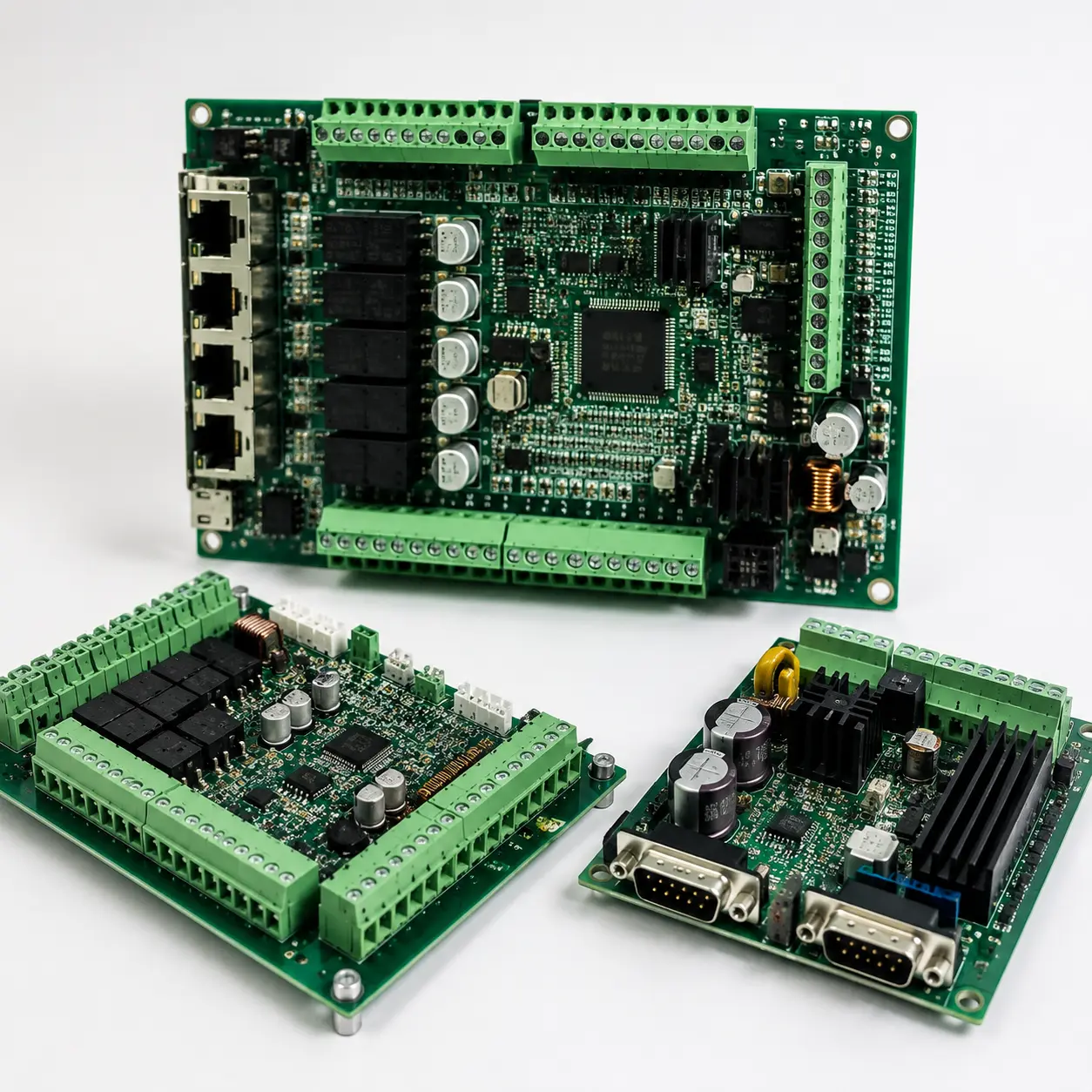
Industrial automation PCB assembly is not judged by the same priorities as a low-duty consumer board. A controller, drive interface, sensor board, or I/O module may need to survive vibration, electrical noise, heat buildup, contamination exposure, long maintenance cycles, and slow component refresh over years of field service.
That changes the release review. Teams still care about cost and schedule, but the bigger question is whether the board will stay stable in a factory setting and whether the manufacturing package gives the supplier enough clarity to build and test it consistently. In practice, this kind of control-board work is usually less about flashy complexity and more about dependable behavior under real operating stress.
This guide explains what teams should review before prototype or production release, where common reliability risks appear, and how to prepare a cleaner handoff for an assembly partner.
Why Industrial Automation PCB Assembly Has Different Constraints From General Electronics
Industrial automation PCB assembly usually supports equipment that cannot tolerate casual downtime. Boards may sit inside cabinets, motor-control systems, PLC-related hardware, HMIs, sensing networks, or power-interface equipment where field replacement is slower and failure analysis is expensive.
That means the review should consider more than whether the board can be assembled once. It should also consider whether the board can be built consistently, inspected clearly, serviced reasonably, and kept supportable across a longer product lifecycle. When teams discuss these assemblies early, they can catch layout and documentation choices that look acceptable in CAD but become weak under vibration, contamination, or maintenance pressure.
A practical starting point is to align the article’s industry context with the broader industries page, then review how the board’s control, interface, and power functions will behave in the real installation environment. In many projects, the board is only one part of a larger system, so the assembly strategy should not ignore enclosure constraints, harnessing, service access, or field diagnostics.
Design and Layout Priorities for Industrial Automation PCB Assembly
Industrial automation PCB assembly starts with layout decisions that support stable operation instead of maximum density for its own sake. Boards that handle mixed signals, power conversion, relays, field wiring, or noisy industrial interfaces benefit from clear zoning, practical creepage and clearance thinking, and connector placement that remains usable after the product is fully integrated.
Key layout checks usually include:
- keeping power, control, and sensitive signal areas organized so troubleshooting and noise control are easier
- leaving practical spacing around larger connectors, terminal blocks, relays, and heat-producing parts
- preserving access for inspection, probing, and rework on high-risk components
- confirming mounting-hole, board-edge, and cable-entry areas do not create mechanical or service conflicts
- avoiding unnecessarily crowded placement that complicates cleaning, coating, or later maintenance
This is also where the project benefits from early discussion about electromagnetic compatibility. Even when formal compliance work happens later, the board layout should already reflect sensible isolation, return-path, and noise-management intent. If those concerns are postponed until after first build, redesign loops get more expensive.
Component, Connector, and Materials Decisions That Affect Long-Term Field Reliability
In industrial control board assembly, component choice is closely tied to service life. A board can be electrically correct and still become a maintenance problem if connectors loosen, terminals are hard to access, or lifecycle continuity was ignored during sourcing.
Connector strategy matters first. Boards that interface with sensors, power lines, motors, or field I/O should use connector approaches that fit the installation and service model. The release review should ask whether wire terminations are robust, whether keyed orientation is clear, and whether technicians can replace or inspect connected assemblies without damaging nearby parts.
Material and protection choices matter too. Some boards may need additional protection against humidity, dust, or chemical exposure, which is why industrial teams often discuss conformal coating before the release package is frozen. Coating does not solve every environmental problem, but if it is likely to be part of the manufacturing route, spacing, keepout, connector masking, and test access should reflect that reality early.
Lifecycle thinking is another major difference. These projects often support products expected to stay maintainable for years, so teams should review whether critical parts are overly single-sourced, whether package changes would break the board, and whether substitutions would create mechanical or thermal side effects later.
Manufacturing and Test Checks Before Release to an Industrial Automation PCB Assembly Partner
A clean release package is especially important for this kind of assembly because the board often mixes electrical, mechanical, and maintenance constraints. If the supplier has to guess which connector heights are fixed, which interfaces are safety-relevant, or which test points must stay accessible, quote speed and build confidence both drop.
Before files go out, the handoff should clearly cover:
- current fabrication and assembly data for the same revision
- BOM clarity, including DNI parts and approved alternates when relevant
- assembly notes for torque-sensitive connectors, coating expectations, or special handling needs
- test intent for programming, in-circuit access, or functional bring-up
- any fixed enclosure, harness, or mounting constraints that affect assembly choices
For industrial automation PCB assembly, test planning should not be left until after the first prototype arrives. If the board will need debug access, fixture support, programming headers, or functional checks tied to control behavior, those needs should be reflected before release. The same is true for supplier coordination through the PCB assembly service page, where early manufacturability feedback can prevent avoidable revision churn.
Common Mistakes That Create Downtime Risk or Expensive Redesign Loops
The most common industrial automation PCB assembly problems are usually not exotic failures. They come from ordinary release habits that are too optimistic for a harsher-duty product.
One mistake is designing connectors and terminals only for schematic completeness, not for installation and service. If cable entry, locking features, labeling clarity, or neighboring part access are weak, the board becomes harder to build and harder to maintain.
Another mistake is treating environmental protection as a downstream option. If the product may face dust, condensation, oils, or vibration, industrial automation PCB assembly should already reflect that through spacing, fastening, connector choice, and process notes before the factory starts preparing the build.
Teams also lose time when they assume a prototype package can stay informal. In industrial control products, prototype runs often set the pattern for later field support. Ambiguous BOMs, missing test notes, and unclear revision control can create problems that repeat well beyond the first batch.
Finally, some teams optimize aggressively for compactness without checking service consequences. Dense layouts can be justified, but if they remove rework access, complicate coating, or hide failure points, the long-term support cost can outweigh the saved board area.
How to Prepare a Cleaner RFQ and Production Handoff Package
A better handoff should help the supplier understand both how the board is built and how it will be used. That usually means combining solid PCB data with a small amount of operational context instead of sending bare files with minimal explanation.
A practical package should include the fabrication set, assembly set, BOM, placement data, revision control, and concise notes on anything that affects industrial handling or field reliability. If certain connectors are fixed, if coating is expected, if there are board-support concerns during test, or if specific interfaces must remain accessible, say so clearly.
It also helps to tell the supplier which items are still flexible. For example, engineering may want feedback on connector spacing, test access, or serviceability before final release. That kind of targeted review is more useful than generic comments after the quote is already underway. When teams need that discussion, the contact page is the right place to start a focused RFQ or manufacturability review conversation.
FAQ About Industrial Automation PCB Assembly
What makes industrial automation PCB assembly different from standard PCB assembly?
Industrial automation PCB assembly usually places more emphasis on environmental durability, connector robustness, lifecycle continuity, maintainability, and stable field behavior. The board must often support longer service expectations and harsher installation conditions than a general-purpose consumer product.
Should industrial automation PCB assembly always use conformal coating?
Not always. The right answer depends on contamination risk, humidity, operating environment, rework needs, and product architecture. The key point is to decide early enough that spacing, masking, connector selection, and test access still make sense if coating is required.
Why is connector planning so important in industrial automation PCB assembly?
Because many industrial boards interact with field wiring, sensors, actuators, or power interfaces that must stay secure and serviceable. Weak connector access or poor mechanical context can create avoidable installation errors and maintenance problems.
When should test access be reviewed for industrial automation PCB assembly?
Before prototype release whenever possible. If debugging, programming, or functional checks matter to product launch and long-term service, the board should preserve practical access before the layout is frozen.
Conclusion
Industrial automation PCB assembly works best when teams review the board as part of a real control system, not as an isolated PCB. Layout zoning, connector strategy, environmental protection, lifecycle continuity, and test access all influence whether the product is easy to build and dependable to support.
When those points are addressed before release, the project becomes more predictable for engineering, sourcing, and the manufacturing partner alike. The result is not just a board that can be assembled, but one that is better prepared for factory use, troubleshooting, and long-term product maintenance.